Sunday, 25 March 2018

COMPACTION FACTOR TEST

COMPACTION FACTOR TEST

AIM - To determine workability of concrete by compaction factor test.

APPARATUS - compaction factor apparatus, scoop, tamping rod, etc.

Theory - The compaction factor test is carried out to measure the degree of workability of fresh concrete with regard to the internal energy required for compacting the concrete thorough.

DIAGRAM - 


Procedure- 
1. place freshly prepared concrete in top mould before noting the mould of empty cylinder(W).
2. open trap door for mould 1. allow concrete to fall in 2nd mould
3.open trap for mould 3 allow concrete to fall in cylinder
4. remove excess concrete
5. note down the partially compacted concrete weight in cylinder after compaction (W1)
6. in same cylinder note down the weight of fully compacted concrete (W2)
7. W2-W/W1-W gives the compaction factor value indiacting the workability of fresh concrete

MARSH CONE TEST
Image result for marsh cone test

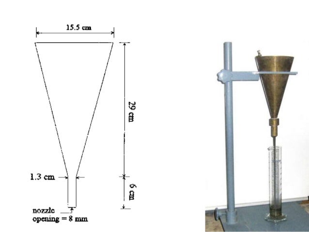
Marsh cone test is reliable and simple method to study the rheological properties of cements and mortars.
• Flow time of cement/mortar through marsh cone is indicator of viscosity, which depends upon cement super plasticizer compatibility.
• It is widely used to study cement super plasticizer compatibility and to determine optimum super plasticizer dosage of a specific cement-super plasticizer combination

Apparatus  It’s consist of a conical brass vessel held on a wooden stand with an orifice of 8mm at its bottom.  A stop watch is needed to measure the time taken by 1 litre of cement or mortar to pass through the vessel.  A mortar mixer is also needed to prepare the cement paste with desired w/c ratio

PROCEDURE  1L of cement paste is prepared in mortar mixer using 2 kg of cement and w/c ratio of 0.32-0.35.High strength Concrete designs typically have w/c ratios less than 0.35.
Water is added in two steps- 70% of water is added in beginning of mixing and rest 30% of water is mixed with super plasticizer, and added afterwards. Cement slurry is prepared with the w/c ratio of 0.32 and admixture dosage of 0.5 %.1 litre of cement slurry is made to flow through marsh cone after 5 min and 60 min of mixing and time in seconds is measured using a stopwatch. The procedure is repeated gradually increasing the S.P. Dosage in steps of 0.2%. Similar tests are conducted for rest of super plasticizers and graphs are plotted with time as Y axis and S.P. dosage as X-axis.

Significance  The saturation dosage of super plasticizer can be defined as that point beyond which there is no significant decrease in the flow time. Saturation point can be taken as the maximum super plasticizer content to be used in concrete. We can implement to use specially recommended admixtures at recommended dosages for given mix design.

Thursday, 15 February 2018

SEWAGE TREATMENT PLANT

SEWAGE TREATMENT PLANT
FLOW CHART OF THE COMPONENTS OF THE 

 SEWAGE

TREATMENT PLANT VISITED

1.RAW SEWAGE Image result for arrow for document 2.SUMP HOUSE PUMP Image result for arrow for document  3.COARSE BAR SCREEN Image result for arrow for document  4.FINE BAR SCREENImage result for arrow for document 5.GRIT CHAMBERImage result for arrow for document   6.WET WELLImage result for arrow for document  7.PUMPImage result for arrow for document  8.INLETImage result for arrow for document  9.AERATION (AIR DIFFUSION METHODImage result for arrow for document 10.SETTLINGImage result for arrow for document  11.CHLORINE
ADDITION Image result for arrow for document  12.KHADI

RAW SEWAGE  

Raw sewage is wastewater that has not been treated. It comes from residential properties, like houses and apartments, as well as commercial buildings and industrial and agricultural processes. Essentially, it is the liquid waste that comes from houses and businesses. Not surprisingly, it can contain a wide variety of contaminants and present a health hazard if left untreated where humans or animals can come into contact with it. For example, sewage may overflow from a sanitary sewer after a period of very heavy rainfall.
 Raw sewage often contains urine and feces from toilet flushing as well as other types of human waste; it may also contain such things as toilet paper

Image result for raw sewage

SUMP HOUSE PUMP

 Sewage lift/pump stations are used for pumping wastewater or sewage from a lower to higher elevation, particularly where the elevation of the source is not sufficient for gravity flow and/or when the use of gravity conveyance will result in excessive excavation and higher construction costs.
 Sewage lift stations/pump stations may be used as a matter of economics or to overcome inadequate hydraulic head when it is obvious that no other solution is practical. For instance, it may be more economical to utilize a sewage pump station to pump or lift the sewage over a ridge and let it flow by gravity to a sewage treatment plant, or to elevate sewage to pass through a sewage treatment system by gravity.


BAR SCREEN:
A bar screen is a mechanical filter used to remove large objects, such as rags and plastics, from wastewater. It is part of the primary filtration flow and typically is the first, or preliminary, level of filtration, being installed at the influent to a wastewater treatment plant. They typically consist of a series of vertical steel bars spaced between 1 and 3 inches apart

Coarse bar screen
Image result for coarse bar screen
Fine bar screen
Image result for fine bar screen


GRIT CHAMBER

A chamber designed to remove sand, gravel, or other heavy solids that have subsiding velocities or specific gravities substantially greater than those of the organic solids in wastewater
Pretreatment may include a sand or grit channel or chamber, where the velocity of the incoming sewage is adjusted to allow the settlement of sand, grit, stones, and broken glass. These particles are removed because they may damage pumps and other equipment. For small sanitary sewer systems, the grit chambers may not be necessary, but grit removal is desirable at larger plants.

Image result for grit chamber ]

AERATION (AIR DIFFUSION)

Fine bubble diffusers produce a plethora of very small air bubbles which rise slowly from the floor of a wastewater treatment plant or sewage treatment plant aeration tank and provide substantial and efficient mass transfer of oxygen to the water. The oxygen, combined with the food source, sewage, allows the bacteria to produce enzymes which help break down the waste so that it can settle in the secondary clarifiers or be filtered by membranes. A fine bubble diffuser is commonly manufactured in various forms: tube, disc, plate, and dome.

Image result for air diffuser AERATION

SETTING TANK

A sedimentation tank allows suspended particles to settle out of water or wastewater as it flows slowly through the tank, thereby providing some degree of purification. A layer of accumulated solids, called sludge, forms at the bottom of the tank and is periodically removed.
Suspended solids present in water having specific gravity greater than that of water tend to settle down by gravity as soon as the turbulence is retarded by offering storage.
Basin in which the flow is retarded is called setting tank.
Theoretical average time for which the water is detained in the settling tank is called the detention period


Image result for rectangular sedimentation tank
CHLORINATION
 Water chlorination is the process of adding chlorine or hypochlorite to water. This method is used to kill certain bacteria and other microbes in tap water as chlorine is highly toxic. In particular, chlorination is used to prevent the spread of waterborne diseases such as cholera, dysentery, typhoid etc
Image result for chlorination in wastewater treatment


DETERMINATION OF INITIAL & FINAL SETTING TIMES

DETERMINATION OF INITIAL &  FINAL SETTING TIMES

AIM - To determine the initial and final setting times of cement

IS CODE - IS: 4031 (Part 5) 1988

APPARATUS - 
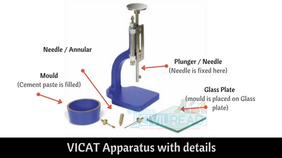
1. Vicat apparatus conforming to IS: 5513-1976. 
2.Balance of capacity 1kg and sensitivity 1 gram. 
3.Gauging trowel conforming to IS: 10086-1982

DIAGRAM:Image result for setting time of cement

PROCEDURE :
1.Unless otherwise specified this test shall be conducted at a temperature of 27 + 20C and 65 + 5% of relative humidity of the Laboratory. 
2.Prepare a paste of 300 grams of cement with 0.85 times the water required to a give a paste of standard consistency IS: 4031 (Part 4) 1988. 
3.The time of gauging in any case shall not be less than 3 minutes not more than 5 minutes and the gauging shall be completed before any sign of setting occurs. 
4.Count the time of gauging from the time of adding water to the dry cement until commencing to fill the mould 
5.Fill the vicat mould with this paste making it level with the top of the mould.  Slightly shake the mould to expel the air. 6.In filling the mould the operator hands and the blade the gauging trowel shall only be used.

Initial Setting Time :
1.Immediately place the test block with the non-porous resting plate, under the rod bearing the initial setting needle. 2.Lower the needle and quickly release allowing it to penetrate in to the mould.  In the beginning the needle will completely pierce the mould
3.Repeat this procedure until the needle fails to pierce the mould for 5 + 0.5mm. 
4.Record the period elapsed between the time of adding water to the cement to the time when needle fails to pierce the mould by 5 + 0.5mm as the initial setting time.

Final Setting Time 
1.Replace the needle of the vicat apparatus by the needle with an annular ring 
2.Lower the needle and quickly release. 
3.Repeat the process until the annular ring makes an impression on the mould. 
4.Record the period elapsed between the time of adding water to the cement to the time when the annular ring fails to make the impression on the mould as the final setting time.


COMPACTION FACTOR TEST

COMPACTION FACTOR TEST AIM - To determine workability of concrete by compaction factor test. APPARATUS - compaction factor apparatus, s...